Isolation distances are not so creepy!

In the first part of this blog “Cleaning up your MOPPs” we looked at the number of means of patient protection (MOPP) that are required at different points in medical electrical (ME) equipment as defined in IEC 60601. The aim being to maintain the single fault safe operation of the device. In this blog we look at the operator safety and the Means of Operator Protection (MOOP) and more precisely the factors that can reduce the protection offered by MOOP. Due to the lack of low impedance to the heart, MOOP have a less stringent rating than MOPP, however MOOP is influenced by several external factors.
There are different ways of realising MOOP (and MOPP):
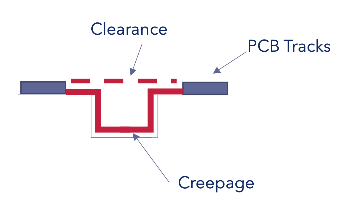
Creepage and clearance distances are perhaps the most challenging of the MOOPs as there are many different factors that can reduce the effectiveness of this type of MOOP.
Anyone working with high voltages in a laboratory environment, will have a rough rule of thumb for when a voltage will breakdown across the surface of a PCB. I spent many hours with a 5kV generator testing isolation barriers in my first role as an engineer. The reality of what is actually permitted for ME equipment is approximately an order of magnitude lower than the nicely controlled lab environment, due to the different reducing factors.
The MOOP tables 13 to 16 in IEC 60601 that specify acceptable creepage and clearance distances are then factored by the following 3 points:
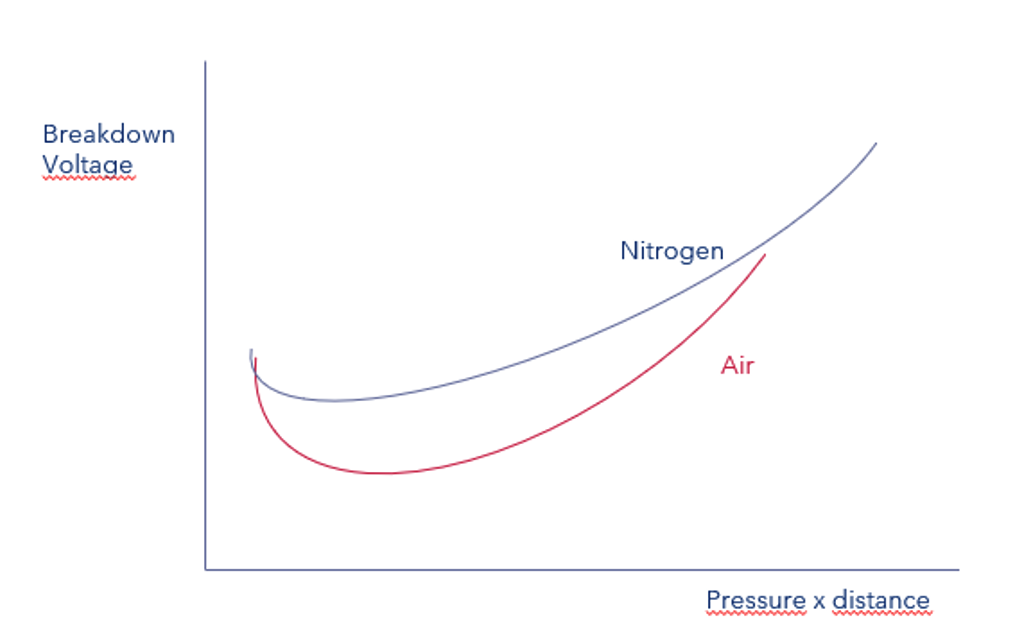
The isolation offered by a defined spacing is not altitude independent. IEC 60664-1 is the document referenced in IEC 60601 for this topic. According to Paschen’s Law the breakdown voltage of a clearance in air is proportional to the distance multiplied by atmospheric pressure. With a factor of 3 times greater clearance required at 10000m in comparison to 2000m in air.
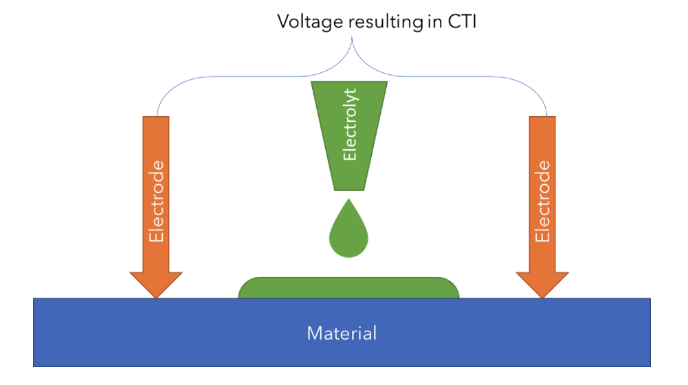
IEC 60601 jumps straight into the subject of comparative tracking indexes (CTI) without explaining what they are how they are defined and more importantly what to expect when defining a PCB to be ordered from suppliers. The standard IEC 60112 provides a series of tests, to define at which voltage a across a given material there will be a breakdown. This utilizes one of 3 different solutions A, B, C which are based on anhydrous ammonium chloride dissolved in distilled water.
50 drops applied to the material under test and then checking at which voltage it will break down. Hence the CTI represents the breakdown voltage from these tests.
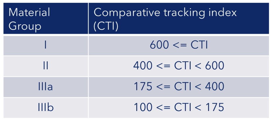
What is a typical CTI for PCBs? FR4 (the most widely used PCB material) is typical 175 i.e. material group IIIa. The CTI can be increased on PCBs by using specific materials.
As defined in IEC 60601 the CTI can represent up to a factor of 2 increase in required creepage and clearance distance when moving from Group 1 to Group IIIa, this is influenced by other factors too.
The next factor that plays a role in scaling the creepage and clearance distances is the pollution degree. As with the other properties there is a sliding scale of reduction in isolation.
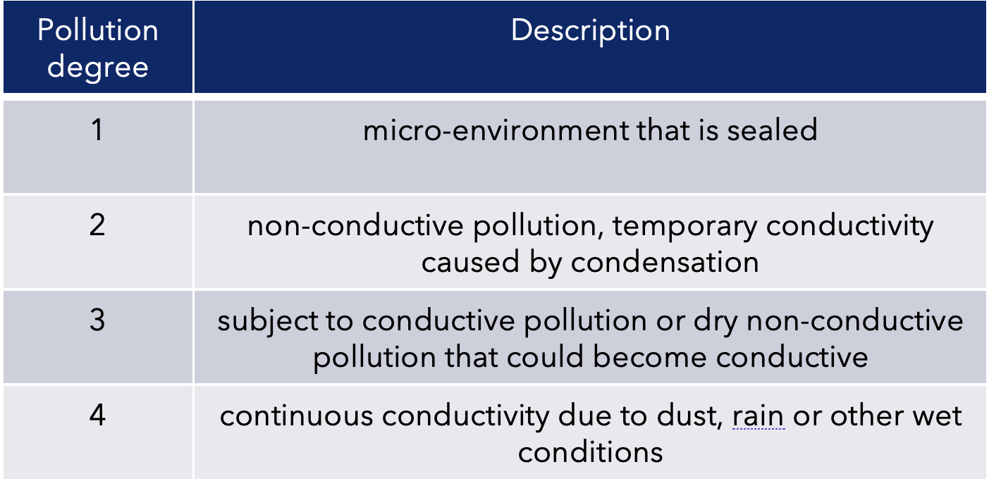
For the same given conditions at a mains working voltage, pollution degree 2 to pollution degree 3 can result in 60% increase in the required creepage and clearance distance.
In this blog we have given a brief introduction to the topic, there are other factors that that influence clearances such as transients through mains supplies.
MOPP from the first part of this blog is handled differently to MOOP in IEC 60601 i.e. the three factors above are not used, but MOPP creepage and clearance is rated higher than for MOOP, before apply the factors.
By Alastair Walker, Consultant & Owner
For more information on the topic of MOOP and MOPP joins us on one of our IEC 60601 training courses or get in touch to discuss your requirements. Please contact us at info@lorit-consultancy.com