Cleaning Up Your MOPPs
One topic that crops up repeatedly in our training courses and when working with customers, is the discussion around the number of means of protection when working with IEC 60601-1.
The means of protection (MOP) is divided into 2 categories:
The aim of IEC 60601 is to justify that the medical electrical equipment (ME equipment) is single fault safe. The analysis of this single fault safe scenario is supported by the use of isolation diagrams. Isolation diagrams enable the mapping out of each point where a single fault could occur i.e. bridging the isolation and hence establishing if there still remains a means of protecting the patient i.e. is the device single fault safe. The isolation diagram then forming an important tool to enable the isolation requirements to be understood and ultimately met.
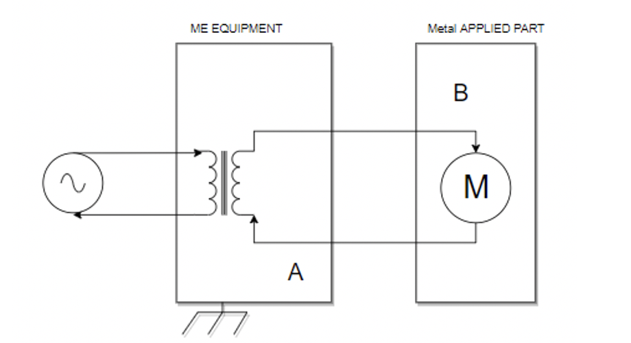
Figure 1 illustrates the case highlighted in Annex A of IEC 60601-1. A short at point A will result in point B becoming ‘live’. The number of means of protection at point A and point B then becomes the focus for the isolation diagram. This was a discussion point from the 2 to the 3 addition of IEC 60601, as there were different levels of protection depending on which point had the single fault.
Where the subject becomes more challenging in IEC 60601 is knowing when to use 1 or 2 MOPPs and how much protection each MOPP should provide. In section 8 of IEC 60601 there are several tables outlining the protection required based on the working voltage. Each MOPP can be implemented using creepage and clearance distances (topic of our second blog in this series), solid insulation or protective impedance. What is more difficult to find in IEC 60601 is how many MOPPs are required in each situation.
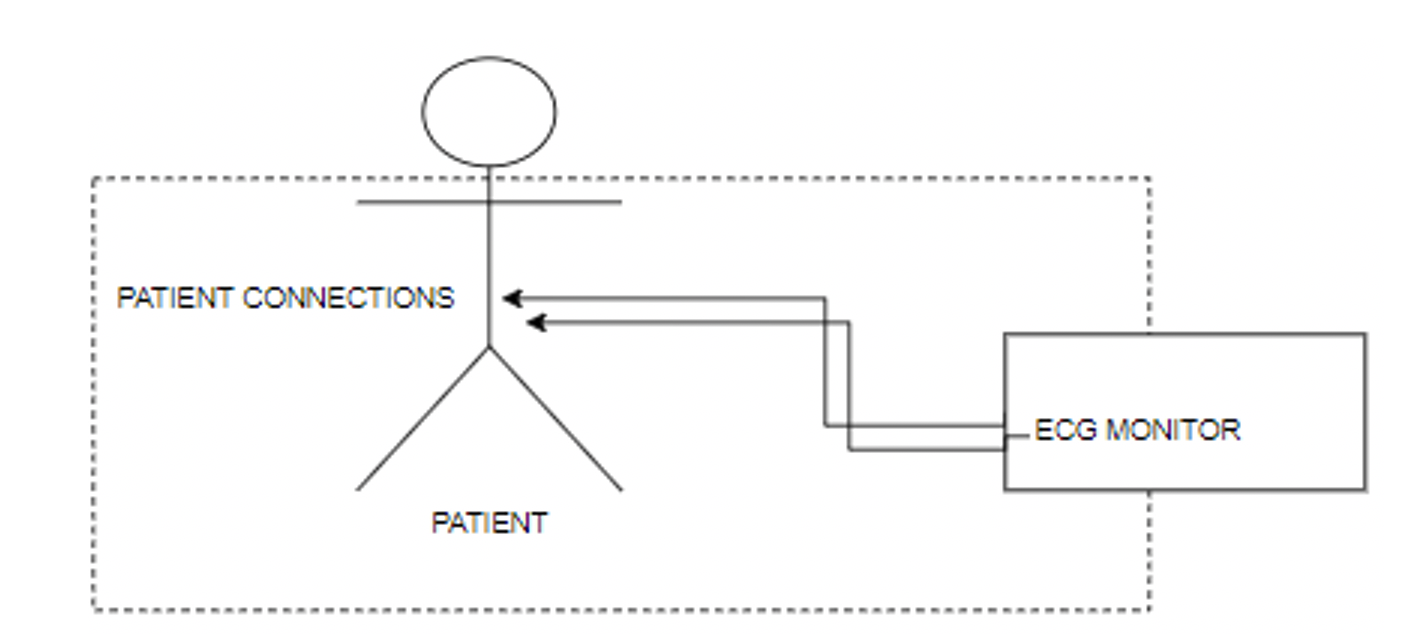
Searching through the standard on means of patient protection yields several points where these topics are covered. In Annex A the number of MOPPs are defined based on the parts electrically connected to the patient (patient connections) and the working voltage. Figure 2 and Table 1 summarise the information:
| Application | Location | No of MOPP |
|---|---|---|
| Figure 2 | Between earth and parts within the dotted line – based on the MAINS VOLTAGE | 1 MOPP |
| Figure 2 | Between earth and parts within the dotted line – voltage carried by these parts (WORKING VOLTAGE) | 2 MOPP |
| Figure 2 | Between live parts (including MAINS) and within the dotted line | 2 MOPP |
| Between ‚functions‘ | Multiple functions = multiple APPLIED PARTS – 8.5.2.1 | 1 MOPP |
| APPLIED PART same function | No separation between the functions | None |
The concerns then highlighted in rows 1 to 3 of Table 1, are focussed on the risk of electrocution either by connecting the patient to earth or to live parts.
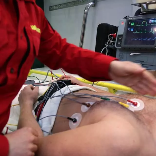
Over and above the items in Figure 2 there are the considerations of multiple applied parts connected to a patient and the isolation between them. The last 2 rows of Table 1 cover the scenario where there may be multiple devices (ME equipment) connected to the patient each with an applied parts. Depending on if these parts are deemed to be separate functions or not will determine if a MOPP is required. In the case of the ECG Monitor the patient connections of that applied parts are the same function hence no MOPP is required between them. This would not be the case if e.g. we had blood pressure and ECG devices operating simultaneously.
The next challenge and the subject we will cover in part 2 of this blog, is how to determine the level of protection each MOPP provides, how these values are derived and then subsequently factored depending on environmental conditions
By Alastair Walker, Consultant & Owner
For more information on the topic of MOP joins us on one of our IEC 60601 training courses or get in touch to discuss your requirements. Please contact us at info@lorit-consultancy.com
Address Austria:
Lorit Consultancy GmbH
Siezenheimer Straße 35
5020 Salzburg / Austria
Address UK:
Lorit Consultancy Ltd
1 Craigathie Road
Roslin Midlothian / Scotland EH25 9BG