Navigating the Complexities of IEC 60664: Key Challenges and Open Questions


Following another fantastic IEC 60664 training course last week, our team was once again met with a series of probing questions from attendees. It’s clear that IEC 60664 is the cornerstone of insulation coordination across many industries and plays a key part in critical product standards such as IEC 60601 (medical electrical equipment) and IEC 61010 (electrical equipment for measurement, control, and laboratory use). However, it still presents several significant hurdles for modern designers.
During our discussions, a few major pain points and open questions consistently came to the surface. Here is a look at some of the primary challenges associated with the standard today, and why an update is long overdue.
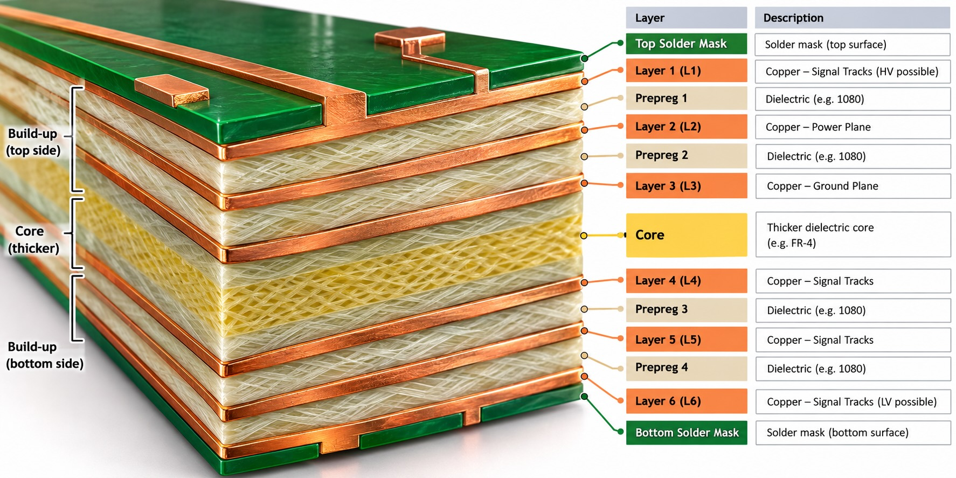
One of the most frequent discussion points centers on the lack of clear definitions within IEC 60664 regarding printed circuit boards (PCBs) versus other types of circuits when evaluating creepage and clearance distances.
Source: AI-generated image created using Google Gemini.
When it comes to PCBs, alternative standards like IPC-2221C tend to handle this far better. IPC-2221C provides a logical build-up of different isolation changes based on real-world manufacturing variables, such as whether solder masks are used, if conformal coatings are applied, and how the overall isolation barrier is systematically constructed step-by-step. IEC 60664 could benefit immensely from adopting a similar, modular approach.
Voltage Difference (Peak DC or AC) | Internal Conductors (Category B1) | External Conductors, Uncoated (Category B2) | External Conductors, Coated (Category B4) |
0 – 15 V | 0.05 mm | 0.10 mm | 0.05 mm |
16 – 30 V | 0.05 mm | 0.10 mm | 0.05 mm |
31 – 50 V | 0.10 mm | 0.60 mm | 0.13 mm |
51 – 100 V | 0.10 mm | 0.60 mm | 0.13 mm |
101 – 150 V | 0.20 mm | 0.60 mm | 0.40 mm |
151 – 170 V | 0.20 mm | 1.25 mm | 0.40 mm |
171 – 250 V | 0.20 mm | 1.25 mm | 0.40 mm |
251 – 300 V | 0.20 mm | 1.25 mm | 0.40 mm |
301 – 500 V | 0.25 mm | 2.50 mm | 0.80 mm |
Above 500 V | Add 0.0025 mm / V | Add 0.0050 mm / V | Add 0.00305 mm / V |
IPC-2221 Table 6.1 – Electrical Conductor Spacing
Note: B1 applies to internal layers, B2 to uncoated external traces, and B4 to coated external traces (e.g., solder mask or conformal coating).
As power electronics evolve, high-frequency performance has become critical. While Part 4 of the IEC 60664 family addresses high-frequency considerations, it remains heavily theoretical and difficult to apply practically.
At higher frequencies, the degradation of insulation capability and required safety margins change significantly:
Homogeneous fields can see a 25% reduction in clearance distance.
Inhomogeneous fields can experience more than a 50% reduction in clearance distance.
Solid insulation suffers a severe reduction in dielectric strength—its short-time breakdown field strength can drop to just 10% of its power-frequency value (a 90% reduction).
Translating these theoretical drop-offs into practical design rules for high-frequency switching applications remains a major challenge for engineers.

Alastair Walker, Owner / Consultant
Have a specific question about applying IEC 60664 to your product? Contact our experts at info@lorit-consultancy.com to discuss your insulation coordination challenges.
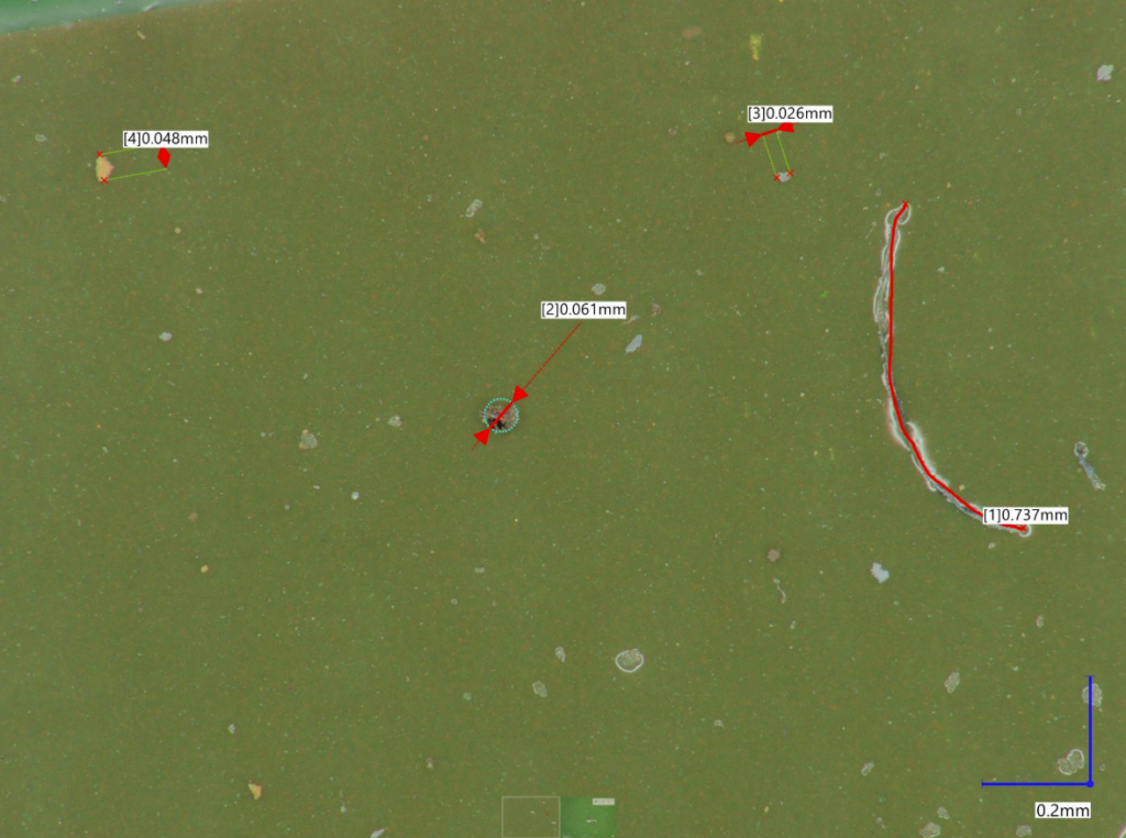
Contamination and particles are mentioned within IEC 60664, but the standard provides virtually no concrete guidance on how to mathematically factor them into creepage or clearance distance calculations. Designers are left wondering how conductive or non-conductive particles of varying sizes and shapes impact paths, yet they are ultimately expected to account for them. Clear, empirical calculation methods for particle pollution would be beneficial.
Source: Image reproduced from the Particle Analysis Report.
Modern PCB architecture involves complex multi-layer constructions, core materials, prepregs, and surface finishes like solder masks. Unfortunately, how these specific board levels and solder mask isolation properties interact and contribute to the overall insulation barrier is not particularly well-handled by the current standard. In particular, calculating creepage distances between tracks of an inner layer of a printed circuit board leaving designers to rely on their own expert judgment for creepage coordination.
Conformal coating and potting represent another area filled with complex design and compliance hurdles. While Part 3 of IEC 60664 specifically addresses protection using coating, encapsulation, or molding, following its prescribed processes in practice is extremely complex and demanding.
Although there are UL-certified combinations available for PCBs, conformal coatings, and solder masks, most customers we speak to find it extremely challenging to fully comply with the stringent evaluation and testing framework laid out in Part 3.
As we look to the future of electronics design, it would be wonderful to see an updated, modernized version of IEC 60664 (and its individual parts) – one that includes explicit methodology for calculating creepage distances between PCB layers. Insulation coordination is an inherently challenging topic, and our training courses and customer consultations consistently reveal just how many open points and misunderstandings still exist across the industry.
By Alastair Walker, Owner / Consultant
Join one of our upcoming IEC 60664 training courses to deepen your understanding of insulation coordination and learn how the standard applies to real-world product design.
Address Austria:
Lorit Consultancy GmbH
Siezenheimer Straße 35
5020 Salzburg / Austria
Address UK:
Lorit Consultancy Ltd
1 Craigathie Road
Roslin Midlothian / Scotland EH25 9BG