Stressed to the Max: Why Failure Rates Tell Only Part of the Story

As a consultancy working on a wide variety of safety and reliability projects, we spend a lot of our time looking at failure rates and failure probabilities. In the world of electronic hardware, there are numerous excellent sources defining failure rates, e.g. FIDES, 217Plus, IEC 61709, and the now–retired (or rather integrated into ISO 26262) IEC TR 62380. For software, there are also sources that can be used to estimate reliability, although it is a difficult subject. Regarding reliability, there are complex strategies in software reliability growth models that can be applied, e.g. those described by Neufelder: How reliable is your software growth? » Lorit Consultancy
However, an area that is often given less focus than it perhaps should is the impact of mechanical and environmental stress. In this blog, we look at how these topics are handled in existing standards and how practical strategies can be used to include these topics in analyses.

Source: Adobe Stock
The typical stress sources that impact devices during normal operational use, as listed in FIDES 2022, are:
Temperature
Electrical stress
Thermal cycling
Mechanical stress
Humidity
Chemical exposure
Additional factors that induce stress include:
Placement – the item‘s position in the equipment.
Application – the operating environment in which the item is used.
Ruggedizing – the level of overstress sensitivity built into the item.
Sensitivity – the overstress sensitivity inherent to the technology of the item.
For most analyses, only a subset of the factors listed above is utilized. Thermal stress based on a mission profile is the most common approach, yielding the Arrhenius relationship over the full temperature range, as indicated below for a Schottky diode.
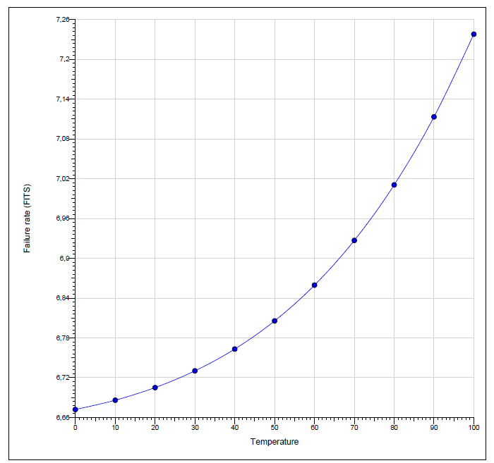
Figure 1. HRC.1913 – Diode, Schottky, 60V, 1A, SOD-123W (Isograph)
Thermal cycling is used in assessing materials such as conformal coatings to ensure that the coating is still effective after this preconditioning. This testing is often performed over a wide temperature range, for example from −40°C to +125°C, with a transition time of 30 seconds between temperature extremes.

Source: Adobe Stock
Relative humidity is a factor that is dependent on knowing 3 key characteristics: the humidity outside the equipment, the temperature outside the equipment, and the temperature rise inside the equipment.
Humidity can play a role in impacting other stress factors. For example, low humidity can significantly increase the charge build up and hence the electorstatic discharge (ESD) voltage magnitude. As relative humidity increases from 10% to 75%, an order-of-magnitude reduction in ESD voltage is possible, with all other reference conditions remaining constant.

Alastair Walker, Owner / Consultant
If your product operates in demanding environments, standard failure-rate predictions may not tell the full story. Contact our experts to identify the most critical stress factors affecting your product’s performance.
Learn moreSometimes humidity-related stress factors are integrated into predified mission profiles. However, from the standards listed above, FIDES has a good approach, using Pecks equation, a stress factor can be defined as a function based both on humidity and temperature.
Humidity reduces with increasing temperature and likewise with increasing altitude.
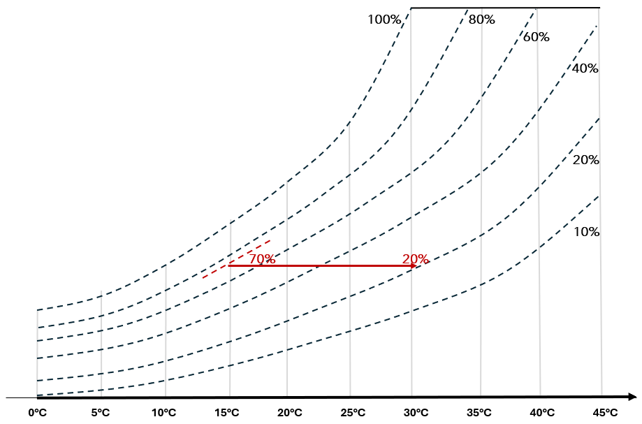
Figure 2. Relation between temperature and humidity
Chemical stress can accelerate other stress factors and can impact insulation materials, having a significant detrimental impact on solid insulation materials. Cleaning of products with more aggressive cleaning materials is another factor that comes into play. This is also a factor in FIDES when looking at printed circuit boards, where multiple chemical stress factors are introduced: saline (continental or coastal area), hermetically sealed, the application pollution level (from inhabited area to engine area), and the environmental pollution level (from rural to urban industrial area).
Chemical stress is modelled qualitatively, as a physical model is difficult to realise for chemical stress.

Source: Adobe Stock
Vibration is the 3rd factor we would like to highlight in relation to mechanical stress. The Basquin equation is used to relate vibration amplitude to the risk of failure in PCBs. However, not all vibration-induced failures result from fatigue, which is the relationship defined in the Basquin equation.
Vibration may also highlight weaknesses in solder joints and PCB delamination. Metalic particles in hermetically sealed cases may result in short circuits as they move around.
The Basquin relationship and hence vibration amplitude are defined in terms of power spectral density (PSD) and defined in terms of g2/Hz with a typical frequency range from 20 to 2000Hz.
A detailed understanding of vibration amplitude is required, as different components and assemblies have different resonant frequencies, depending on their physical characteristics.
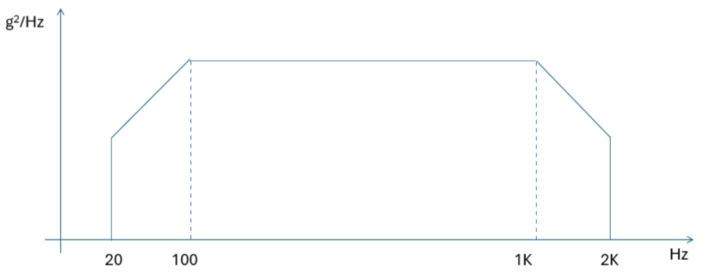
Figure 3. Basquin equation
Ultimately, the best strategy will depend on the product and the environment in which it is used. However, predefined mission profiles based on aviation, automotive, or other applications may not necessarily be the best approach to analysing stress in your product. You may choose to define each type of stress and how to quantify it on a case–by–case basis, particularly if chemical or humidity stress is a primary concern.
By Alastair Walker, Owner / Consultant
Contact us for bespoke consultancy on how to improve confidence in your product’s reliability!
Address Austria:
Lorit Consultancy GmbH
Siezenheimer Straße 35
5020 Salzburg / Austria
Address UK:
Lorit Consultancy Ltd
1 Craigathie Road
Roslin Midlothian / Scotland EH25 9BG